- The Story
- What to Buy
- Troubleshooting Your Program
- Making LEDs Work
- Reading Potentiometers
- Servo Jitters
- Ethernet Shield
- Using Eclipse
- Troubleshooting
Eclipse
May 2013 - I have made an
experimenter's kit for the
AlaMode board that will also work nicely with other Arduinos.
September 2009 - A few months back I got bit by the bug
to play with microprocessors again. It's been years (like 30 years) and I
wondered if I still had what it takes. So far, the answer is yes. This page
serves two purposes. First, it is here to share with the world little tips I
picked up or figured out as I relearned how to make an Arduino do what I want.
Second, and perhaps more importantly, this page is meant to be a note pad so
that I remember it too!
I have a pretty good understanding of basic electronics. When I was in high
school I spend many hours pouring over books of theory on tubes - that's right -
and transistors. My first year of college I studied electronics. I remember a
class in - gasp - analog computers. (I think they were just a pile of capacitors
and resistors.) One great class was using the 8080 SDK. We loaded our little
programs in hex from a keypad. I became disenchanted with electronics when I
found that my designs, while correct, would not work because some component was
out of spec. Grrrr. Then I took a class in computer science, where everything is
deterministic and I fell in love. I loved the low level computer code where
interrupts and and multiple threads make the situation incredibly complex.
Still, failures in this world are not caused by a resistor that is 900 ohms
instead of 980 ohms.
Coming back into the microprocessor world I found the much has changed in 30
years. For $60 I was able to buy an assembled microprocessor board with a boot
loader and a USB board to connect it all to my laptop. The development software
is open source with many examples. Spending a few bucks at Fry's for LEDs and
resistors I was able to blink lights in about 10 minutes of work!
Enough about me, here are the tips.
Q: What should I buy to get started?
A: You have two ways to go.
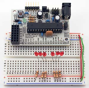
 I bought an assembled Bare Bones Board (BBB) from ModernDevice. I asked them to put in the
pins pointing under the board for plugging into a bread board. I also bought
the USB BUB.
The BUB board connects to the six pin connector on the BBB. You can then connect
a cable from the BUB to a USB port on your PC. It provides power to the Arduino
and makes it easy to send your software down to it. This board seems easier to
hook up to the breadboard, but it might not be as good when you want to deploy a
final solution because the pins are pointed down.
I bought an assembled Bare Bones Board (BBB) from ModernDevice. I asked them to put in the
pins pointing under the board for plugging into a bread board. I also bought
the USB BUB.
The BUB board connects to the six pin connector on the BBB. You can then connect
a cable from the BUB to a USB port on your PC. It provides power to the Arduino
and makes it easy to send your software down to it. This board seems easier to
hook up to the breadboard, but it might not be as good when you want to deploy a
final solution because the pins are pointed down.
With the BBB solution you'll have to go to your local electronics store to
buy a bread board, wire, LEDs and other components as you need them. I remember
looking at all the LEDs at Fry's and thinking, which should I get? Oh, I guess
these. I glanced at the back of the package and it had a list of different
resistors recommended for the different voltages. Hmmm. The Arduino runs at
5vdc, but the package listed 3v, 6v, 12v. I got the one for 6v and it worked. It
was humbling that I didn't even remember I would need resistors. I have a lot to
recall.
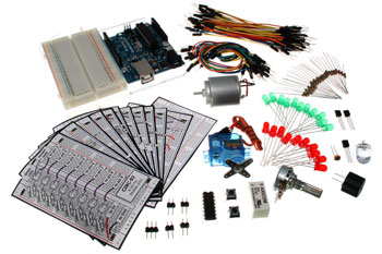 If you are really a beginner, then I'd buy an Arduino experimentation
kit that includes servos, motors, potentiometers (like volume controls), and
LEDs. AdaFruit
has a good one. I think the standard Arduino board that comes assembled in these
is good for use in your finished products. I should have bought this kit.
If you are really a beginner, then I'd buy an Arduino experimentation
kit that includes servos, motors, potentiometers (like volume controls), and
LEDs. AdaFruit
has a good one. I think the standard Arduino board that comes assembled in these
is good for use in your finished products. I should have bought this kit.
Q: Why a resistor with a LED?
A: LEDs are diodes. Current flows one way, and not the other. Once current
starts to flow and the LED lights up, it has very little resistance. With little
resistance, it will let lots of current flow. With lots of current flowing, it
will burn up. Putting a resistor in series with the LED limits the current flow.
Read the back of the LED package to know what resistors you need. My LEDs needed
a 1.2K ohm resistor at 6vdc.
Q: Troubleshooting programs with Serial.print.
 A: I was using the sample program for blinking a LED and
wanted to extend it to do more things. I'm using the Arduino development
environment (IDE). On the far right is the Serial Monitor button. After
compiling and downloading your program, click this button. That will reset the
Arduino and begin monitoring the serial port. If you put the following in your
program
A: I was using the sample program for blinking a LED and
wanted to extend it to do more things. I'm using the Arduino development
environment (IDE). On the far right is the Serial Monitor button. After
compiling and downloading your program, click this button. That will reset the
Arduino and begin monitoring the serial port. If you put the following in your
program
Serial.print ("hi there");
then when your program executes this line you will see "hi there" in the
bottom of the IDE. I guess this seems simple now, but when I was just getting
started I didn't know you could do this. I was flashing LEDs to give me a hint
about what my program was doing. Doh!
Q: Potentiometers: Linear or Audio Taper
A: Linear. You can read the value of a potentiometer (pot) with the
analogRead function. It returns a value from 0 to 1023 with 0 when the input pin
is to ground and 1023 when it is to 5v. A linear taper pot will change gradually
as you twist it. An analog taper pot will vary slowly at first, then quickly
towards the end. To read the value of the pot I used this code in my main
loop:
int valNow = analogRead(potPin);
if
(abs(valNow - valOld) > 10) {
Serial.println(valNow,DEC);
valOld =
valNow;
}
My concern was that the main loop runs too fast and I didn't want to just
flood my IDE with the prints. Instead I only print when the value has changed by
at least 10.
My first time I used a 10k ohm audio taper pot. I connected one side of the
pot to VCC and the other side to ground. The middle pin I connected to an analog
input pin on the BBB. This was a bad idea because when the pot was turned to min
I was essentially shorting the analog input to ground. I put a 1k ohm resistor
between the low side of the pot and ground to fix this. But now when the pot was
at min the middle lead was not at ground due to the resistor. I tried to fix
this by subtracting 200 from the value of the analogRead. Then I found that the
sensitive part of the pot was too sensitive. By barely touching the pot the
value would jump. I tried to compensate by using the sqrt of the value, but that
just got more and more crazy. I went to the store again.
With a 10M ohm linear pot in place things worked better. When the pot was at
min, the value was almost 0 as well. This works because the 5vdc is split across
the pot and the resistor by their ratio. So the voltage on the min lead of the
pot is now (1K/(10M+1K)) * 5 which is pretty close to 0.
But then Gary gave me some advice. First, there's no problem shorting an
input to ground. Inputs are high resistance (impedance) so they don't draw a lot
of current. I could eliminate that 1K ohm resistor. Second, since the input is
high resistance, I should use a low esistance potentiometer. He recommended a 1K
pot. Here's a page on how I think the theory
makes that correct.
Q: Switch needs a resistor
An input pin should not be left hanging. You should always have it tied to
either +5v or to Ground. One side of a push button switch is attached to an
input pin and a 10k resistor. The other side of the resistor is connected to
ground. The other side of the switch is connected to +5v. When the switch is
open the pin is tied low. When the button is pushed, the pin is tied high. The
resistor is needed so that when the switch is closed you're not shorting 5v to
Ground. In this configuration the pin is never left floating.
What about a toggle switch? You could use the same configuration. When the
toggle is on you will be bleeding power through the 10k ohm resistor constantly.
Is that an issue?
E=IR
I = E/R
5/10000 = 0.0005 or one half a
milliamp
I think we're ok.
An interesting post by Halley about the need for a resistor on an input pin,
summarized here: The Arduino reference page on the topic mentions putting 100
ohm between the input pin and just about anything. It's not absolutely
necessary, but here's a situation that could cause damage to the ATmega: wire a
pin straight to HIGH, configure your input as an output, and write a LOW to the
output. If the pin is configured as an input (analog or digital), it will not
be damaged by direct connection to true HIGH or true LOW. Note that pins are
configured as input by default and thus avoid a problem until your program
starts running. When configured as input the pins draw very little current - as
if they had 100M ohm resistance.
Exceeding AREF on analog inputs by a significant amount might cause
damage. ATmega pins have an internal 20k pullup resistor which you can use by
setting a pin to input and then write it high.
Here's
an excellent reference. If you use the internal pull up resistor remember
that part of the total Vcc will fall across this resistor and will thus affect
the maximum reading you can get from your pin.
Q: Output Pins
Pins in output mode are low impedance and can supply 40mA. Shorting an output
pin to the opposite of its setting can burn the pin out. You should always have
a 470 ohm resistor in series with an output pin.
Q: Servo jitters
A: I bought a motor
party add on kit from adafruit. Given my still not working LAN shield I
decided to hook the servos to the BBB directly.
First up, these servos have three wires. Brown is ground, Red is 5vdc, Orange
is the control. You control the position of the servo by sending pulses of
different widths. For example in your main loop:
digitalWrite(servoPin,HIGH);
delaymicroseconds(2000);
digitalWrite(servoPin,LOW);
delay(20);
// give the servo time to move into position
will position the servo pretty far around. Servos typically take from 0 to
2500 microsecond pulses corresponding to 0 to 180 degrees. This site has a nice
explanation.
My servo was jumping around like a cricket. After much consternation I
noticed that the LED on the BBB was flickering. Ahh. I had moved the jumper to
make the bread board rail 5v come from the BBB voltage again. Apparently every
time the servo motor moved it was pulling enough current to lower the BBB
voltage and the BBB was going through a reset. I moved the jumper and the
problem got better, but my trusty Radio Shack voltmeter put between VCC rail and
ground showed that the voltage was still being pulled low.
I also realized that this could be screwing up my potentiometer reading as
well. Since my application was measuring the voltage differential to ground, if
the voltage is being pulled down by the servo, then the pot reading would go
lower. My program would read the pot and then adjust the servo position. As you
turned the pot the servo would turn. If the rail voltage changed, then so would
my reading, and I would change the pulse width I was sending to the servo.
Sometimes this would settle down to a stasis. Other times when the servo stopped
the voltage went back up and my program changed the pulse width. The servo would
move, pulling down the voltage again, and my program would change the pulses
again. The servo would chatter back and forth between two little positions.
My Radio Shack multimeter showed that the servo draws over 150 milliamps when
it moves. My power supply brick was only rated for 300. I went back to Fry's and
bought an 1800 milliamp supply. I also bought a second bread board so that the
servo power could be isolated from the others.
Now I still get a few jitters. Someone has suggested that the power supply
voltage may not be completely steady and that might cause the servo to keep
repositioning. I'm going to try putting a capacitor between the VCC and ground
rails hoping that it will reduce any ripple in VCC. LATE BREAKING NEWS: With the correct potentiometer now in place my
reading of the tap voltage is rock steady. It maybe varies by 1 or 2 over time;
that's nothing. I updated my code to ignore an absolute change less than 2 and
now the servo action is really smooth.
Jim Schrempp is a sometimes freelance writer (only Vanity Press will publish
his work) living in Saratoga, California. His writings have appeared on numerous
pages on his own web site. The opinions expressed in this piece are those of the
writer and do not necessarily represent those of anyone else (although Jim
wishes more people shared his opinions)